A 250-foot wheel, assembled upright. Follow the lift, close the rim, and explore the forces.
Historical reconstruction · engineering estimatesUPPER RIM1 model unit = 1 foot
3D could not start on this device. The sequence, calculations, dimensions, and source plates remain available below.
Permanent steelTemporary works*Lift / force
Drag to orbit · pinch / scroll to zoom · two fingers to pan
*Temporary works, rope routing, erection increments, and connection details are schematic. Animation time is compressed.
THE OPENING DATE / 1893
The fair opened. The wheel wasn’t ready.
The exposition opened May 1. Passenger service began June 21: 51 elapsed calendar days later. This is the gap to the fair opening, not a verified variance against a recovered contractual baseline. [3]
FROM THE JOB / JUNE 9–10
Rice reported a successful twenty-minute revolution on June 9. The next day Ferris pressed for faster car installation and round-the-clock work. Mechanical success still left passenger equipment and finishing work to complete. Read the telegram transcriptions [3].
A production schedule built around the evidence.
The solid diamonds below are dated evidence. Hatched bars are reconstructed work windows. Tower, axle, rim, drive, and handover durations are adjustable teaching assumptions. They are calibrated to June 9 and June 21, not recovered daily records. January 1 is only a plotting start for winter work.
Schedule logic, quantities, and limits
The illustrative branch is: foundation release → towers (14 days) → axle (2) → rim (59) → adjustment and first rotation (6). Mechanical installation overlaps from March 20 and reaches readiness on June 9. First rotation waits for both branches. A further 12 days represents car hanging, finishing, tests, and opening preparation, with overlap within that window. All values are calendar days, not shifts or crew-days.
Thirty-six rim positions over 59 assumed days implies 0.61 positions/day. Thirty-six cars over the 12-day opening window implies 3 cars/day including other work; neither is an observed gang rate or a pick count. Six cars on June 11 is a dated progress observation, not proof of uniform car production. Crew counts, labor hours, daily deliveries, weather losses, and the original critical path remain unresolved. The model assumes downstream durations do not recover lost time.
FOUNDATION BREAKOUT / ONE TOWER FOOT
The work below ground.
Rice describes three feet of frost, saturated sand, pumping, steam thawing, and piles passing through blue clay to hardpan about 32 feet below grade. Steel beams and concrete formed the foundation above them. Steam thawed the frozen ground; it did not melt the mineral sand. [1]
ONE REPRESENTATIVE FOOT / SCHEMATIC
Drag to orbit · scroll or pinch to zoom
Drag to orbit · scroll or pinch to zoom
3D is unavailable. The assembly steps and source comparison remain available.
Brown: ground / pilesBlue: steel / anchorsGrey: concrete
What can we say about the design?
| Record | Reported foundation | Use in this model |
|---|---|---|
| Rice, 1901 [1] | Steel beams in concrete over piles; hardpan 32 ft below surface | Pile-supported assembly and 32-ft bearing horizon |
| Scientific American, July 1, 1893 [2] | Four feet per tower; 20 × 20 × 20-ft concrete foundation at each foot; bottom steel crossbars and iron anchor rods | One representative 20-ft cube; eight feet in overall tower model |
| Hyde Park Historical Society [4] | Eight piers reported as 20 × 20 × 35 ft | Conflicting depth retained as an unresolved account |
No verified foundation drawing has been located for this study. The 20-ft block is a visualization choice from contemporary reporting. Nine visible piles and two orthogonal beam layers illustrate the load path; they do not establish the actual pile pattern or grillage design. Excavation support and placement lifts are not resolved. No soil bearing, pile capacity, or concrete quantity is calculated from this uncertain geometry.
133 YEARS BEFORE THIS STUDY
A wheel built by people.
The design carries Ferris’s name. Its completion also depended on the people who made, shipped, inspected, hoisted, fitted, and operated it. The record names the superintendent and suppliers more readily than individual workers. Their names and gang sizes are not invented here.
In the shops
Rice describes fabrication distributed among a dozen firms with inspectors checking work before shipment. Fit mattered because much assembly first occurred on site. [1]
In the ground
The underground assembly required excavation, pumping, pile driving, steel placement, and concrete work. Winter conditions made the foundation a production problem before the first tower post could be erected. [1, 2]
Above the Midway
The surviving erection plates show timber staging and tackle. The visible work includes building access and supports, handling the axle, fitting rim sections, and attaching cars. Look at the people in the original illustrations for a sense of scale. Inspect the erection plate [2].
Getting it to run
Steam power, drive machinery, brakes, car installation, and testing turned an erected structure into a passenger attraction. The June telegrams preserve the pressure to finish. [1, 3]
These are descriptions of the work, not a verified roster of trade jurisdictions or a claim that 1893 methods match present-day practice.
FW-EP-001 / SAMPLE / REV 0
Plan the work behind the wheel.
A planning exercise using the study’s historical sequence. Starts after foundations are accepted. Quantities, package boundaries, staffing, rates, and durations below are illustrative. This is not a recovered 1893 schedule or an approved field erection procedure.
Five shifts per week. Whole shifts rounded up by package. Gang size changes labor only, not production. A rim position covers both wheel planes and connecting work; it is not one piece or one crane pick. No tonnage-derived pick count is assumed.
| Package / show in model | Work window | Basis | Release to next operation |
|---|
01 / Delivery and assembly
Receive and identify tower steel, axle/hubs, rim components, rods, and cars by package. Keep the axle staging area separate from rim preassembly and car storage. Reserve access for hoisting equipment and a clear delivery route outside the assembly footprint.
Prepare a piece-and-pick register with mark, package, verified weight, center of gravity, lift points, pickup/set coordinates, rigging, and connection release criteria. The 36 rim positions do not establish the number of lifts.
02 / Hoisting strategy
The historical study uses tackle and falsework. No modern crane model or capacity is selected here. For a modern alternative, first resolve the axle/hub assembly, lift height, pickup and set radii, boom clearance, ground support, rigging deductions, and the governing chart configuration.
The study’s 140-kip axle/hub value is a historical model input, not a verified lift weight. Confirm the actual assembly and all attachments before equipment selection. Tower steel, rim units, and cars each need their own lift definition.
03 / Temporary works and stability
Before steel erection, issue a stage-by-stage temporary works design covering foundations, towers, falsework, open-rim stability, lateral restraint, wind limits, and access. Define the permitted sequence and stop-work conditions for each incomplete state.
Rim closure is a hold point, not permission to remove support. Establish connection acceptance, geometry, spoke adjustment, monitored load transfer, and support-release order before changing the load path.
04 / Resources and handoffs
The sample raising gang covers tower, axle, rim, and car packages. A separate six-person temporary works crew covers initial staging and later release; a four-person mechanical crew covers drive/brake installation and commissioning. Survey, inspection, supervision, operators, and other support are additional and excluded from labor totals.
Drive/brake work overlaps rim work using a separate crew and access zone. Release and commissioning are sequential. The sample assumes no shared equipment conflicts; resolve those before treating the schedule as resource-loaded.
Planning gates and scope of this sample
- Foundation acceptance: survey, concrete acceptance, anchors, and geotechnical/temporary bearing conditions released.
- Axle lift: approved lift procedure, verified gross load, hoist/support capacity, rigging, communications, and weather limits.
- Each rim increment: specified connections complete; geometry and temporary restraint accepted before the next increment.
- First rotation: engineered support transfer complete, drive and brakes accepted, swept area clear, controlled test procedure authorized.
- Car hanging: engineered loading order and rotation restraints; do not infer balance from the animation.
- Handover: inspection, testing, deficiencies, and operating acceptance complete before passenger service.
The schedule excludes foundations, design, procurement, fabrication, transport, weather allowances, contingency, and public-opening approvals. Holds have no allowance for failed inspections or redesign. Track “erected” separately from connection completion, inspection, and package release.
Historical basis: Rice’s account and the source plates support the broad progression. All resource and production values in this plan are modern sample assumptions. The model’s timeline is illustrative progress, not elapsed schedule time.
FOLLOW THE LOAD
The mechanics behind the spectacle.
Change an assumption. See the consequence.
1 kip = 1,000 lbf · 1 short ton = 2,000 lb
ILLUSTRATIVE TWO-TACKLE MODEL
Reeving, efficiency, rigging allowance, and load split are adjustable assumptions. Eight parts is an example, not a recovered rigging specification.
W* = (Waxle+hubs + Wrigging) × DAF
QA = s W* QB = (1 − s) W*
T ≈ Q / (n η)
QA = s W* QB = (1 − s) W*
T ≈ Q / (n η)
The tackle reduces the pull in its running rope. It does not divide the load carried by the whole support tower. The head reaction also depends on the dead-end attachment and lead-line direction; a downward lead from the same support adds approximately its line pull.
This is static equilibrium with a lumped efficiency. Individual rope-part tensions, anchors, timber capacity, and axle bending are not solved.
COMPLETE WHEEL / GRAVITY ONLY
Default rotating steel weight is a rough back-calculation: 2,400 − 140 − 36 × 26 − 1,440 × 0.150 = 1,108 kips. The 1,200-ton loaded total and 13-ton cars come from contemporary reporting, not a quantity takeoff. “Ton” is interpreted as US short ton here.
W = Wsteel + Waxle+hubs + 36(Wcar + Nwperson)
RA = RB = W / 2
RA = RB = W / 2
Equal reactions assume the center of gravity is midway between the two bearings along the axle. Cars can be uneven around the circumference and still split their vertical load equally across the two towers.
During rim assembly, the load path is different. Temporary supports share the load with the hub. The stage panel therefore gives a reaction range, not a falsework analysis. Before rim closure, do not treat the incomplete wheel as a finished tension wheel.
These are bearing reactions, not individual footing reactions. Tower self-weight, wind, dynamics, leg bending, anchor forces, foundation stiffness, and soil capacity are excluded.
ADDED LOAD / COMPLETED WHEEL
Amber cars mark added loads. This is a hypothetical distribution, not the documented car-hanging order. 26 kips represents one empty car; 6 kips represents forty 150-pound riders.
Mgravity = −Σ (ΔWi × 125 sin θi)
Frim,equivalent = |M| / 125
Frim,equivalent = |M| / 125
The opposing drive or brake torque must balance gravity at rest. Equivalent rim force is the net tangential force, not the tension in either drive chain. Inertia, friction, wind, chain geometry, and drive losses are excluded.
A historical learning model, not an erection design or structural certification. No finite-element analysis is implied. Member sizes, connections, material properties, pretension, and temporary support conditions are incomplete.
EVIDENCE BEFORE ANIMATION
What the record actually supports.
Was the wheel tripped upright?
Rice’s account describes an axle hoist followed by rim sections added from the bottom in both directions, closing at the top. It does not describe tipping an assembled wheel upright. [1]
The 1893 plates show timber falsework and multi-part hoisting tackle. Their arrangement informs the scene, but exact rope counts, anchor locations, pick weights, and tower-leg erection methods are unresolved. [2]
Scale, with the uncertainty left visible.
All three axes use feet at the same scale. Major geometry follows the values below. Bracing topology, support member sections, rigging, platforms, foundations, and cabin details are simplified. Thin rods have a minimum visual line width. Orthographic views preserve projected scale.
| Element | Model | Basis |
|---|---|---|
| Outer diameter | 250 ft | [1, 2] |
| Axle center height | 140 ft | [1, 2], approximate |
| Modeled rim top | 265 ft | 140 + 125; Rice reports 264 ft |
| Wheel-plane spacing | 28.5 ft | [1]; [2] rounds width to 30 ft |
| Inner rim radius | 80 ft | [1]; [2] implies 85 ft |
| Axle / hub diameter | 32 in / 16 ft | [1, 2] |
| Axle length | 45 ft | [1, 2], rounded |
| Cars / panels | 36 / 36 | [1] |
| Car envelope | 26 × 13 × 9 ft | [1]; [2] gives 27-ft length |
| Tower base / top | 40 × 50 / 6 × 6 ft | [2]; orientation inferred |
| Axle + hubs weight | 140 kips default | [1], 70 short tons |
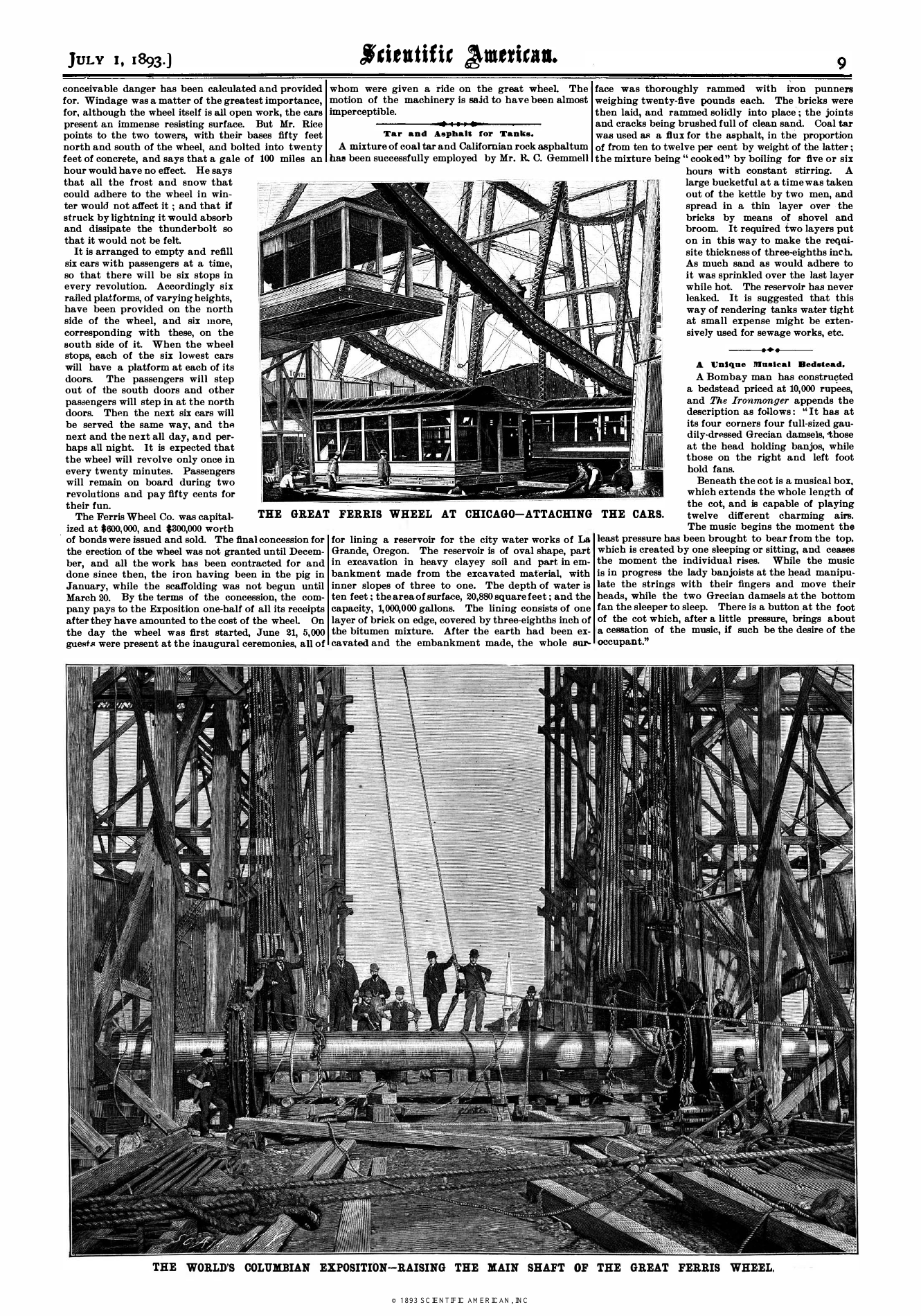
Original erection illustrations, July 1, 1893. Tap to inspect the full plate. See the falsework plate.
Primary sources
[1] Luther V. Rice, “Ferris Wheel,” 1901, pp. 475–480. Construction superintendent’s account, in the Report of the Committee on Awards of the World’s Columbian Commission. Read the transcription.
[2] Scientific American, July 1, 1893, pp. 8–9. Contemporary article and erection illustrations; its text abstracts the Chicago Tribune. Read the original scan. Tribune transcription and historical images.
[3] Chicago History Museum, History Lab: “Talking with Telegrams.” June 9–10, 1893 Rice–Ferris telegram transcriptions (PDF pp. 7–9), plus historical background. Read the correspondence. Originals are linked, not reproduced.
[4] Hyde Park Historical Society, Ferris Wheel history. Later foundation account; dimensions conflict with contemporary reporting. Read the account.
Conflicting rounded dimensions are retained above. Calculated results are modern estimates from the stated assumptions; they are not Ferris’s recovered calculations.
THE WHEEL & THE MAN BEHIND IT
Chicago’s answer to the Eiffel Tower.
01 / THE IDEA
A bridge builder thinks bigger.
George Washington Gale Ferris Jr. was a civil engineer whose work included steel frameworks for bridges and tunnels. He graduated from Rensselaer Polytechnic Institute in 1881 and built his career in Pittsburgh. When Daniel Burnham challenged American designers to rival the Eiffel Tower at Chicago’s 1893 World’s Fair, Ferris proposed an enormous revolving observation wheel. [H1] [H2]
Smaller amusement wheels already existed. The audacity was the scale. Organizers were skeptical, and Ferris had to secure technical backing and investors before the proposal could become a construction job. [H2] [H3]
02 / THE DEBUT
A new view of the city.
The wheel opened on June 21, 1893. Its 36 passenger cars could carry up to 60 people each. More than 1.4 million people paid 50 cents to ride during the fair, the same price as admission to the exposition itself. For many, this was an extraordinary opportunity to see Chicago and Lake Michigan from high above the ground. [H1] [H3]
The animation above explores the work behind that experience: foundations, steel towers, temporary staging, the axle lift, and a rim assembled upright. Construction superintendent Luther V. Rice’s account is one of this study’s primary sources.
03 / AFTER THE FAIR
The name outlived the wheel.
The attraction’s success did not give Ferris a happy ending. Disputes over the proceeds led to litigation, and he died in 1896. [H2]
The wheel was dismantled and re-erected on Chicago’s North Clark Street, where it operated from 1895 to 1903. It was then moved again for the 1904 St. Louis World’s Fair. In May 1906, it was demolished with dynamite and sold for scrap. The original structure disappeared, but the Ferris name stayed with the ride. [H3]
Read more about the history
[H1] Rensselaer Polytechnic Institute, “Circles in the Sky”. Ferris’s education, the fair’s challenge, and the passenger experience.
[H2] Lemelson-MIT, “George Ferris”. His career, the proposal, financing, and later litigation.
[H3] Chicago Architecture Center, “Chicago’s Ferris wheel story”. The attraction’s reception, relocations, and demolition.